at90usb 5by5 devboard
The basic idea with this design is to make a devboard:
- That fits within 5x5cm (= cheap bords from iTead/iStore or Seeedstudio).
- It uses Atmel at90usb162 (because i got bunch to last really cheap).
- Easy to make your own accessories for it (hence IDC-10 connection).
Sections
Hardware
Rev A
Newer made any boards of this. No schematics or layouts will be released.
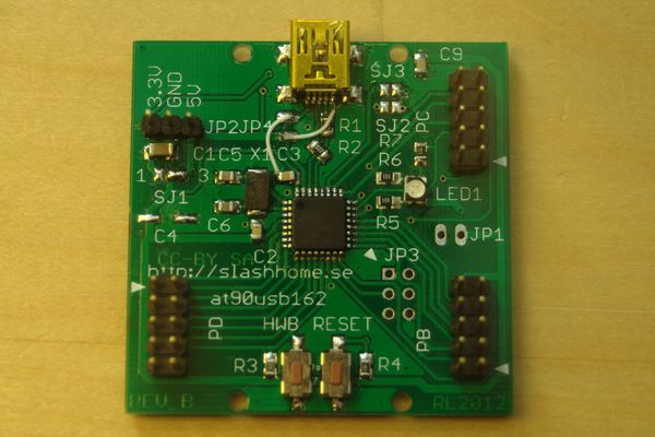
Rev B
MAJOR BUG: VCC and GND on USB is crossed, will DESTROY at90usb162 if not patched (the boards I made is patched and tested).
First board made (10pcs).
Images of schematic and PCB is in the gallery below. I win't release the schematic due to the severity of bugs, please wait for Rev C. or mail me if you really want it.
Signals
The I/O ports is called PB, PC and PD. Pin 1 is marked with an arrow. Only connect one power source at a time.
- signal - connection on board
- PB0 - PB:1
- PB1 - PB:2
- PB2 - PB:3
- PB3 - PB:4
- PB4 - PB:5
- PB5 - PB:6
- PB6 - PB:7
- PB7 - PB:8, LED(blue)
- RESET(PC1) - PC:1 (if SJ2=shorted), 'RESET'-button
- PC2 - PC:3
- PC4 - PC:5
- PC5 - PC:6, LED(green)
- PC6 - PC:7, LED(red)
- PC7 - PC:8
- PD0 - PD:1
- PD1 - PD:2
- PD2 - PD:3
- PD3 - PD:4
- PD4 - PD:5
- PD5 - PD:6
- PD6 - PD:7
- PD7 - PD:8, "HWB"-button
- 5V - PB:10, PC:10, PD:10, JP1:1
- 3.3V - PC:4 (if SJ1=shorted), JP1:3
- GND - PB:9, PC:9, PD:9, JP1:2
Rev C, Rev D
No boards made. Was messing around with different ideas, like integrated prototype area. But nothing i ever really settled with.
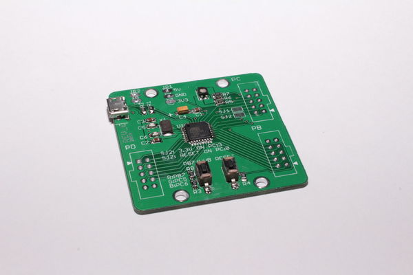
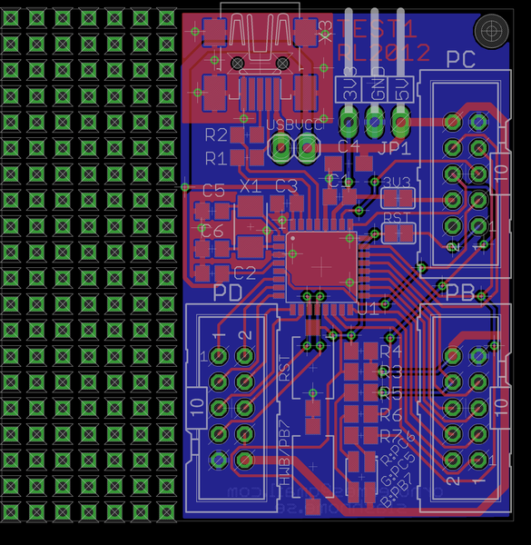
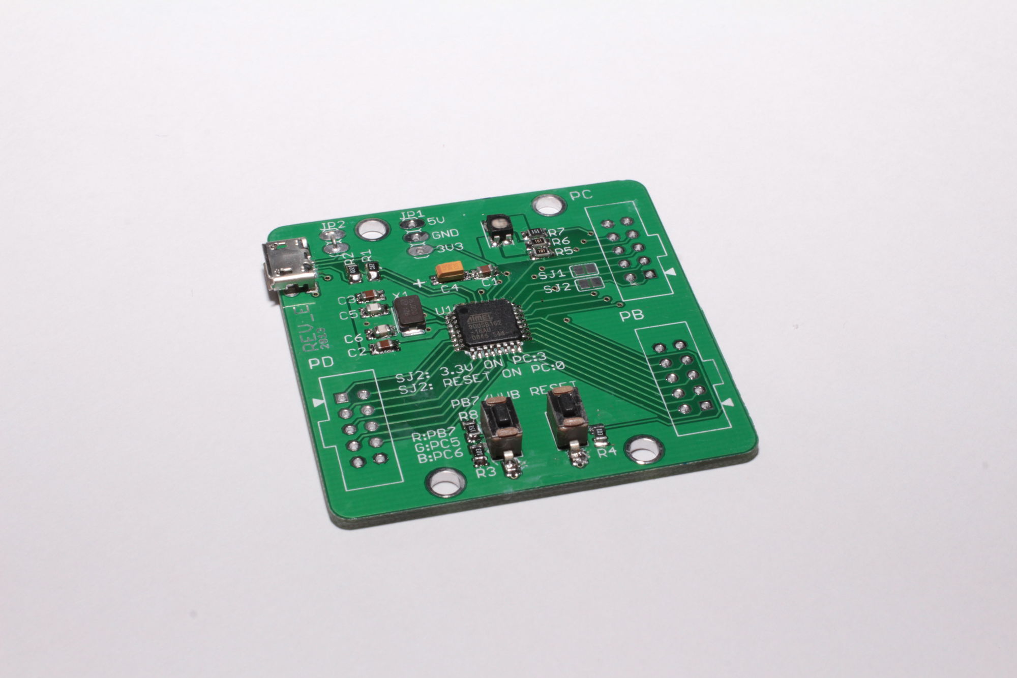
Rev E
I noticed Seeedstudio have a laser cutting service that sparked a chain of ideas. First of i wanted to try it and I got the idea to make a case for a new revision of my board. The board layout is pretty cleaned up to make it as good looking as possible. Here are some of the changes:
- I removed the capability to make it in to a 3.3V board (without serious hacking), which isn't really relevant as it among other things requre a slower crystal.
- I removed the ISP header. I have never needed it as the MCU is it's own programmer.
- The headers are now matching up with a 0.1" grid so it can be used easy with proto boards.
- With the laser cut cover the board is quite protected, you don't have to be too worried about it getting shorted while laying on your desktop or pins getting bent in your back pack.
- Switched red and blue LED GPIO pins.
- Moved to Micro USB connector as they are supposed to be more durable and are becoming more common
BUG: The bottom laser cut plastic are missing holes for JP1 and JP2.
Signals
The I/O ports is called PB, PC and PD. Pin 1 is marked with an arrow. Only connect one power source at a time. The only difference from rev B that should matter regularly is that the red and blue LEDs has switched GPIO pins.
- signal - connection on board
- PB0 - PB:1
- PB1 - PB:2, JP3:3(SCK)
- PB2 - PB:3, JP3:4(MOSI)
- PB3 - PB:4, JP3:5(MISO)
- PB4 - PB:5
- PB5 - PB:6
- PB6 - PB:7
- PB7 - PB:8, LED(red)
- RESET(PC1) - PC:1, JP3:5(RESET), 'RESET'-button
- PC2 - PC:3
- PC4 - PC:5
- PC5 - PC:6, LED(green)
- PC6 - PC:7, LED(blue)
- PC7 - PC:8
- PD0 - PD:1
- PD1 - PD:2
- PD2 - PD:3
- PD3 - PD:4
- PD4 - PD:5
- PD5 - PD:6
- PD6 - PD:7
- PD7 - PD:8, "HWB"-button
- VCC - PB:10, PC:10, PD:10, JP3:2(if JP1=shorted)
- 5V - PC:2 (if SJ2=shorted), JP2:3
- 3.3V - PC:4 (if SJ3=shorted), JP2:1
- GND - PB:9, PC:9, PD:9, JP2:2, JP3:6
Accessories
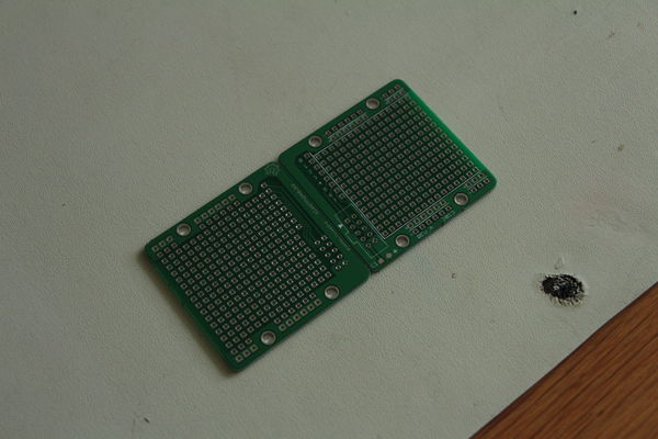
Proto board
A small and simple prototype board with IDC10-connector.
Rev A
Made at the same time as the at90usb162-board rev E. There is a risk of shorting stuff as it's through plated. Requires most wires to be insulated. But it's still quite useful.
Software
Linux
Ubuntu (and most debian based systems)
Open an terminal and run this command (you type the bold parts):
$ sudo apt-get install git-core gcc-avr avr-libc dfu-programmer
That will install what you need to download some sourcecode, compile, and flash this board.
Now we need somewhere to work. First make sure you're in your home directory. Then crate a new directory.
$ cd ~
$ mkdir source
$ cd source
Now let's download the example source from github.
$ git clone git://github.com/ornotermes/at90usb-board-tester.git
$ cd at90usb-board-tester/
Let's compile the code.
$ make hex
On some systems you don't have permissions to access Atmel USB devices as a regular user. In that case you will get errors like "Permission denied" or similar when trying to upload firmware, if you have problems later on try this:
$ wget http://slashhome.se/files/98-all-your-atmel-belong-to-us.rules
$ sudo cp 98-all-your-atmel-belong-to-us.rules /etc/udev/rules.d/
$ sudo service udev restart
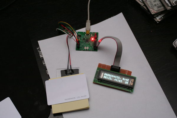
Connect your board.
To make the board enter programming mode you have to press HWB and RESET, then while still pressing HWB releasing RESET. Check if you can find the device. One of the lines should look similar to the one below the command.
$ lsusb
Bus 003 Device 006: ID 03eb:2ffa Atmel Corp.
And at last flash the board.
$ make dfu-program
If you get "dfu-programmer: no device present." check that the device actually has entered programming mode.
Press reset on your board to exit the bootloader mode and run the program.
Windows 7
Download and install WinAVR, Atmel FLIP.
Connect your board.
To make the board enter programming mode you have to press HWB and RESET, then while still pressing HWB releasing RESET.
Windows will now try to install the DFU driver. If it fail:
- Right-click Computer and select Manage.
- Select Device Manager.
- Right-click AT90USB162 DFU and select Update Driver Software....
- Click Browse my computer for driver software.
- Click Browse.... Select your Flip installation folder (i.e. C:\Program Files (x86)\Atmel\Flip 3.4.7 and click Next.
- Click Install.
Now let's download some sample code. Now you have several options:
- github for Windows. Simple if you want to use github and not any other git servers.
- Git for Windows. If you want to use gitservers other than github.
- Download ZIP-file of example code.
I will focus on the github for Windows.
Download and install github for Windows.
Sign up and sign in to github for Windows. Sign in to github in your web browser.
Go to example code and click Clone in Windows. Now the source will be cloned to a local repository on your computer.
When complete click the right-arrow (open this repo) next to ornotermes/at90usb-board-tester in your github for Windows-window.
Click on tools and select open a shell here.
Let's compile the code. Run this command (you type the bold parts):
> make hex
Make sure your board is in boot-loader mode.
And at last flash the board.
> make program
Press reset on your board to exit the boot-loader mode and run the program.
Files
| Filename | Description | License |
| 98-all-your-atmel-belong-to-us.rules | Give users permission to Atmel usb devices. | ? |
| 5by5_at90usb162_rev_e.zip | Eagle files and drawing for laser cutting (SVG) of 5by5at90usb162 rev E. | CC BY-SA |
| 5by5_proto_rev_a.zip | Eagle files of 5by5proto rev A. | CC BY-SA |
Links
AVRLibc documentation
Datasheet and Appnotes
LUFA (Lightweight USB Framework for AVRs)
How to give users permission to Atmel devices
WinAVR
Atmel FLIP
Git for Windows
github for Windows
My example code
Bitwise operations in C